STM32 Code Download via ST-Link Tutorial: Wiring, Driver, and Keil Configuration Complete Guide

A complete guide to flashing code to STM32 via ST-Link using the SWD interface.
This article details the complete process of downloading code to STM32 via ST-Link: first connecting the ST-Link to STM32 through 4 SWD wires (3.3V, SWDIO, SWCLK, GND); then installing the ST-Link driver and confirming recognition in Device Manager; next configuring ST-Link Debugger in Keil and verifying the connection; finally compiling and downloading the program, then pressing Reset to verify LED blinking confirms successful flashing.
Introduction
For beginners just getting started with STM32 development, successfully downloading code to the chip is the very first step. Based on a Bilibili creator's STM32 HAL Library + AI Smart Car tutorial series, this article provides a detailed walkthrough of the complete process for flashing code to an STM32 chip using an ST-Link, covering hardware wiring, driver installation, Keil configuration, and download verification.
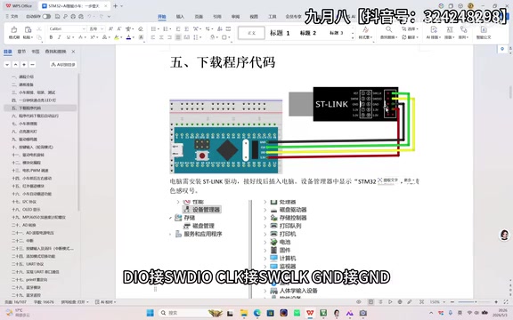
Hardware Connection: SWD Wiring Between ST-Link and STM32
ST-Link is the officially recommended debug programmer for STM32, communicating with the target board via the SWD interface. Only 4 wires are needed to complete the connection, with the following pin mapping:
| ST-Link Pin | STM32 Pin |
|---|---|
| 3.3V | 3.3V |
| SWDIO | DIO |
| SWCLK | CLK |
| GND | GND |
SWD Interface Technical Background
SWD (Serial Wire Debug) is a two-wire debug interface protocol designed by ARM specifically for Cortex-M series processors. It uses only two signal pins — SWDIO (data line) and SWCLK (clock line) — to perform complete debugging and programming operations. Compared to the traditional JTAG interface which requires 5 signal pins (TDI, TDO, TMS, TCK, TRST), SWD significantly reduces pin usage, freeing up GPIOs for other peripheral functions. The SWD protocol is based on the ARM Debug Interface v5 (ADIv5) architecture, accessing the chip's internal debug resources through the DAP (Debug Access Port). It supports all debug functions including breakpoint setting, single-step execution, and memory read/write, with performance identical to JTAG. This is why SWD mode has become the most mainstream method for STM32 download and debugging.
When wiring, make sure the power pins are not reversed, as this could damage the chip or the programmer. It's recommended to first confirm the pin names marked on the development board's silkscreen, then connect them one by one.
ST-Link Driver Installation and Device Recognition
After completing the hardware connection, you need to install the ST-Link driver on your computer; otherwise, the computer won't recognize the programmer.
How the ST-Link Debugger Works
ST-Link is an in-circuit debugger and programmer officially released by STMicroelectronics. It internally integrates an STM32 chip as its main controller. It communicates with the PC via USB interface, converting debug commands from the host into SWD or JTAG protocol signals sent to the target chip. ST-Link supports multiple operating modes, including online debugging (Debug), In-Circuit Programming, and mass production flashing. Common versions on the market include ST-Link V2 and V3, with V3 supporting higher communication speeds and a wider target voltage range. Many STM32 development boards (such as the Nucleo series) already have ST-Link circuitry onboard, eliminating the need to purchase a separate programmer.
Driver Installation Steps
- Download the ST-Link driver (available from the ST official website or the tutorial's companion cloud storage)
- Run the installer and follow the prompts to complete installation
- Connect the ST-Link to your computer via USB cable
Verifying Device Recognition
After installing the driver, confirm that the computer correctly recognizes the ST-Link device:
- Right-click "This PC" → Click "Manage"
- Go to "Device Manager" → Expand "Universal Serial Bus devices"
- Check if "STM32 ST-Link" appears in the list
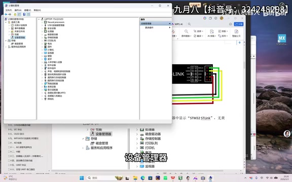
Key Indicator: If there is no yellow exclamation mark or warning icon next to the device name, the driver installation was successful. If a yellow exclamation mark appears, you need to reinstall the driver or try a different USB port. Windows may sometimes fail to recognize the device due to insufficient USB port power supply or driver conflicts — in such cases, try using a USB port on the motherboard's rear panel rather than the front panel.
Configuring ST-Link Debugger in Keil Project
Once the device is recognized successfully, proceed to configure the debugger in the Keil development environment.
Introduction to Keil MDK Development Environment
Keil MDK (Microcontroller Development Kit) is an embedded development toolchain under ARM, and one of the most widely used IDEs for STM32 development. It integrates the μVision editor, ARM Compiler, debugger, and simulator components. Keil supports chips from different manufacturers through DFP (Device Family Pack), and users need to install the corresponding STM32 DFP pack for development. For debugging, Keil supports multiple debug adapters including ST-Link, J-Link, and ULINK, providing a unified debugging experience through the CMSIS-DAP standard interface. The compiled firmware files are typically in .hex or .axf format, written to the chip's Flash memory via the debugger.
Selecting the Debugger Type
- Click the "Debug" option in the toolbar (or access it through Options for Target)
- Select "ST-Link Debugger" from the debugger dropdown list
Connection Verification
Click the "Settings" button to enter the ST-Link configuration interface:
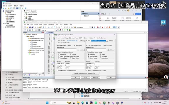
If the interface displays a serial number consisting of letters and numbers, it means Keil has successfully connected to the target STM32 chip through the ST-Link. This serial number is the unique identifier of the ST-Link device — each ST-Link has a unique serial number programmed at the factory, which can be used to distinguish between different programmers when multiple devices are connected simultaneously.
Key Configuration Changes
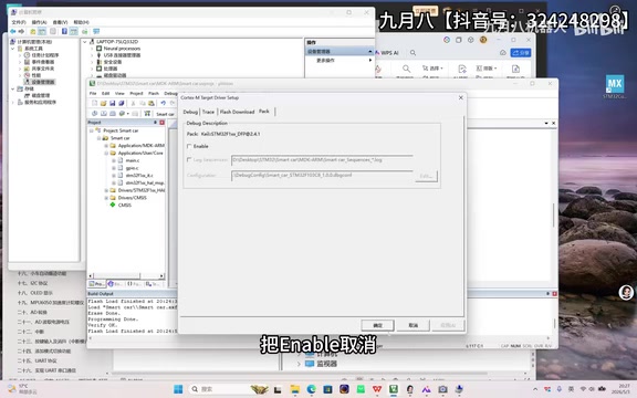
In the settings interface, find the option with "Unable" in its label and uncheck it. This step ensures that the program will automatically run after download is complete. Click "OK" and "OK" sequentially to save the configuration.
Compiling, Downloading, and Verifying
STM32 Flash Programming Mechanism
STM32 programs are stored in the on-chip Flash memory, which is non-volatile memory that retains data after power-off. The flashing process actually involves the ST-Link sending erase and program commands to the Flash controller, writing the compiled binary code to the specified address space. STM32 Flash typically starts at address 0x08000000, and upon power-up, the chip reads the interrupt vector table from this address and begins program execution. Flash programming requires erasing before writing, with erasure performed in units of sectors or pages. This is why there's a brief wait time during each program download — the system needs to complete three steps: erase, write, and verify.
Executing the Code Download
Once configuration is complete, the workflow is very straightforward:
- Compile the project: Click the Build button (or press F7), ensuring no compilation errors
- Download the program: Click the Download button (or press F8) to flash the firmware to the STM32
- Reset and run: Press the Reset button on the development board
Reset Mechanism Explained
STM32 reset is an operation that restores the chip to its initial state — all registers return to default values, and the program begins executing from the Flash start address. STM32 supports multiple reset sources: external pin reset (pressing the Reset button), Power-On Reset (POR), Brown-Out Reset (BOR), software reset, and watchdog reset. The Reset button on the development board is connected to the chip's NRST pin; pressing it pulls the pin low to trigger a reset. The purpose of unchecking the relevant option in Keil configuration is to control whether the chip automatically resets and runs after download is complete. Different versions of Keil and ST-Link firmware may describe this option slightly differently.
Verifying the Download Result
If everything is configured correctly, after pressing Reset you should observe the LED on the development board starting to blink, indicating that the program has been successfully downloaded and is running. This LED blink experiment is the classic "Hello World" of embedded development, signifying that the development environment setup is complete. The LED blinking is essentially the program controlling the GPIO pin's high and low voltage levels, combined with a delay function to achieve periodic on/off effects.
Common Troubleshooting
If the download fails, troubleshoot in the following order:
- Wiring issues: Check that all 4 wires have good contact and correct pin correspondence. Poor dupont wire contact is the most common issue beginners encounter
- Driver issues: Check if ST-Link has a yellow exclamation mark in Device Manager; try uninstalling and reinstalling if necessary
- Power supply issues: Ensure the STM32 development board has stable 3.3V power. Some boards require additional USB power, as the ST-Link's 3.3V output alone may not provide sufficient current
- Keil configuration: Confirm that the correct debugger type and chip model are selected, and that the DFP pack version matches
- USB port: Try different USB ports on your computer to avoid poor contact. Prefer USB 2.0 ports, as some USB 3.0 ports may have compatibility issues
- ST-Link firmware: If the ST-Link firmware version is too old, use the ST-Link Utility tool to perform a firmware upgrade
Summary
The core workflow for downloading code to STM32 via ST-Link can be summarized as: Correct wiring → Install driver → Configure Keil → Compile and download → Reset and verify. Once you've mastered this basic operation, you can build upon it for more complex project development, such as AI smart cars and other embedded applications. While the process may seem to involve many steps, once the environment is configured, subsequent development iterations only require repeating three steps — compile, download, and verify — making it highly efficient.
Key Takeaways
- ST-Link connects to STM32 via SWD interface using only 4 wires: 3.3V, SWDIO, SWCLK, GND
- SWD is a two-wire debug protocol designed by ARM specifically for Cortex-M, saving pins compared to JTAG while maintaining full functionality
- After installing the ST-Link driver, confirm there's no yellow exclamation mark warning in Device Manager
- In Keil, selecting ST-Link Debugger and seeing a serial number in Settings confirms successful connection
- The "Unable" option must be unchecked to ensure the program runs properly
- Programs are flashed to Flash memory (starting address 0x08000000) and persist after power-off
- After compiling and downloading, pressing Reset and observing LED blinking confirms successful flashing
Related articles
 Tutorials
Cursor + Codex Dual-IDE Collaboration: A Practical Methodology for Open-Source Project Customization
A complete methodology for open-source project customization based on real-world experience, detailing the Cursor+Codex dual-IDE workflow, seven-stage process, MVP validation, and AI source code reading techniques.
 Tutorials
Cursor Multi-Agent in Practice: Building a Full-Stack Next.js Blog in 50 Minutes
Build a full-stack blog in 50 minutes using Cursor IDE's multi-Agent mode with Next.js, Clerk auth, and Supabase. Learn the 4-phase AI Agent workflow and key integration pitfalls.
 Tutorials
Building an AI Software Factory from Scratch: A Cursor Engineer's Hands-On Experience with Multi-Agent Collaboration
Cursor engineer Eric shares practical insights on building an AI software factory: automation levels, guardrail design, parallel Agent management, and scaling to 1000+ Agents for 24/7 development.